Here’s how I took an Arduino Uno, some FOSS software, and created a Winter Wonderland.
For those of you who’ve been living under a rock, the “maker community” has been flourishing over the last few years. At the heart of it all lies very small, very cheap microprocessors. These microprocessors generally have only a few KB of storage and memory. But what they lack in power they make up for in breadth of utility. With one of these gizmos, you can make almost anything. I put one to work flicking my Christmas lights off and on in sync with a few holiday classic tunes. Here’s how I did it.
The Main Ingredients
One of the most popular is the Arduino family of microcontrollers. You can get the Uno model for less than $30 if you buy from a Chinese manufacturer. See, Arduino did us all a huge favor and released the plans on how to build their products under an open-source license. That means anyone is free to manufacture their product and sell it as their own. I’ve got official Arduino boards and the Chinese “knockoffs” and they both work just fine. However, depending on which manufacturer you buy from, your mileage may vary.
This experiment benefited from yet another open-source project, the Vixen Lights software. While Vixen 3 is the current release (and actively maintained), Vixen 2 is still around and in use by some in the community. And yes, there is a community of dudes (I’m assuming) who tinker around and spend gobs of money and time making their house the coolest on the block during Christmas time. I found DIYXmas forum and remain very grateful for the help those guys provided helping me get everything working.
Now that I’ve mentioned Arduino and Vixen, it’s probably a good time to explain how they tie together and make the magic happen. Vixen serves as the “brains” of the operation, firing off neurons down to the Arduino, who acts as the “muscle”. Vixen sends serial data to the Arduino via USB, and the Arduino performs the instructions (which in our case is making lights go blinky blinky). Let’s take a deeper look at what’s going on, shall we?
Software That’s Free (As In Beer AND Freedom)
Vixen (unfortunately) only runs on Windows. It also depends on a specific version of the .NET framework (which it’ll probably have to download) as well as Java, so sit back and watch the LOTR trilogy whilst it downloads. Once installed and opened, you’ll have to set up a ‘display’, which serves as a software representation of your actual light display. Each element of your display has to be mapped to a ‘channel’ of the software. Think of an element as the smallest, stand-alone unit of your display (e.g. a tree wrapped with lights or each post on your front-porch). An element can be independently turned on and off, or grouped together in an arbitrary manner (e.g. if each bush is an element, you can group all bushes into a ‘bushes’ group or group each post into a ‘posts’ group).

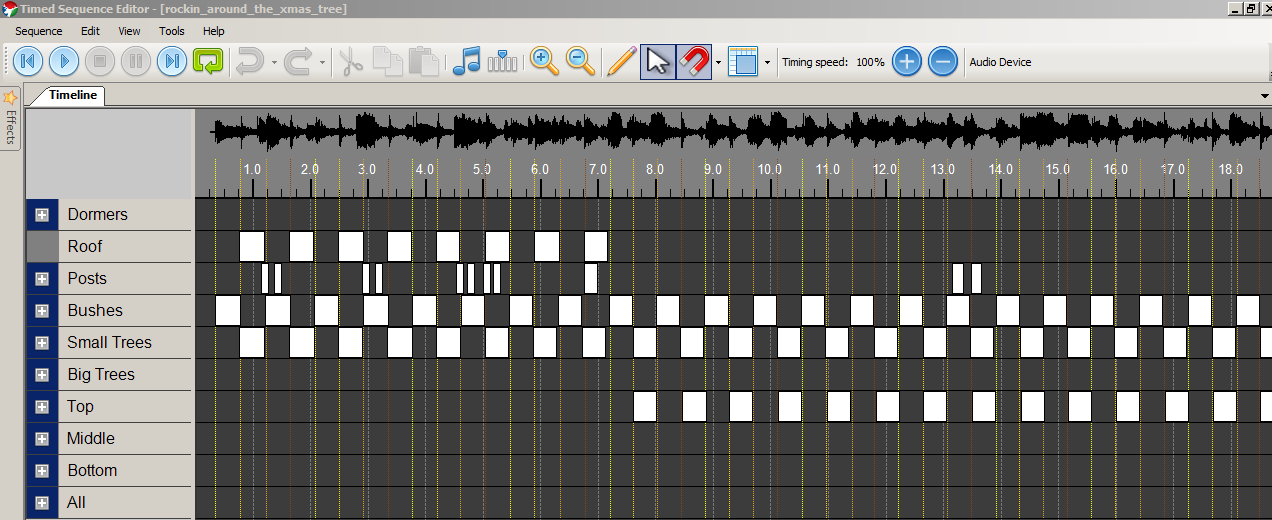
First, import an mp3 into Vixen. It’ll generate a waveform, giving you visual clues as to what’s going on in the song. I also used Audacity to analyze the mp3 and exported an XML file with the “down-beats” of the song (i.e. the first beat of the measure). After importing that file into Vixen, an overlay of those beat-marks are shown on the project time-line (see Figure 1 below; the yellow lines are from the Audacity file). This is all in an attempt to get the lights flashing at the right time.

Now that we know where the down-beats are, we can begin orchestrating our light show. This will require some creativity. I can’t really explain WHAT to do, but I can tell you HOW to do it. In Figure 1, you’ll note that the project is broken up into rows. Each row represents an element in the display. This is all set up in the configuration that I won’t go into in this post. See those white boxes in Figure 1? As the “head” of the music player sweeps from left to right when you hit play, if there’s a box underneath the head, that element gets turned on. You can see that my boxes (ahem roughly) line up with the yellow beat-marks. So every 50ms, Vixen says “OK, Dormers 1-3, Roof, & Bushes…you’re ON!”. The Arduino, waiting on the other end of the USB cord, interprets these instructions and flicks the Dormers 1-3, Roof, & Bushes lights on. They’ll stay on until Vixen tells the Arduino to turn them off in a later packet. Figure 2 shows how each element in the software is mapped to the Serial message. I had to play around to figure out which plug to use for each element, but once I got it I marked the cords with a Sharpie so I won’t have to figure it out again next year.
While we’re on the topic, here’s the code that the Arduino is running. In short, it’s listening for a Serial packet. Once received, it turns on/off each channel of lights. Rinse and repeat.
1 2 3 4 5 6 7 8 9 10 11 12 13 14 15 16 17 18 19 20 21 22 23 24 25 26 27 28 29 30 31 32 33 34 35 36 37 38 39 40 41 42 43 44 45 46 47 48 49 50 51 52 53 54 55 56 57 58 59 60 61 62 63 64 65 66 67 | |
Many thanks to Scott Shaver for all of the great videos and code that got me interested in this whole project. OK, so that’s a rough overview of the software side. Now, let’s take a look at the hardware.
Hardware
The hardware components I used are as follows:
- A used electrical service box (like one you’d find on a construction site; they’re water-resistant).
- An [Arduino Uno r3] or equivalent. As long as there’s at least 16 digital I/O ports.
- Two Sainsmart 8 channel 5V Solid State Relay (SSR) boards. At the time of publication, these were listed as $28.59…I paid maybe half of that. Shop around.
- 5’ of Romex wire and a bag of 3-way jumpers
- 16 indoor/outdoor extension cords
- 2’ of 22 gage jumper wire to connect the Arduino to the SSR units.
- A small screwdriver and a regular sized screwdriver (no soldering, yay!).
- A piece of plexi-glass, some machine screws, and nylon risers
The Box
I found an old, slightly rusty service box at my grandpa’s house. I sanded the rust spots and spray-painted it to protect the metal. This would serve as the housing for the Arduino and the two 8 channel solid-state relays. Another benefit of using a service box is that there’s a plate on the front that, while easily removable, can still be screwed in place to prevent the unknowing from touching any of the dangerous parts inside.
 Figure 3: Housing
The Arduino
Again, I used an Arduino Uno R3, but any microcontroller with at least 16 digital I/O pins will suffice. Once the code from above has been loaded, Vixen is able to send Serial data to it. As packets come in, the Arduino responds accordingly, flipping it’s little 5V pins off and on (hopefully in sync with your song). “But, how are you able to power 110V indoor/outdoor Christmas lights when the Arduino can only push 5V out?”, you ask? Well, that’s where the SSR’s come in to play.
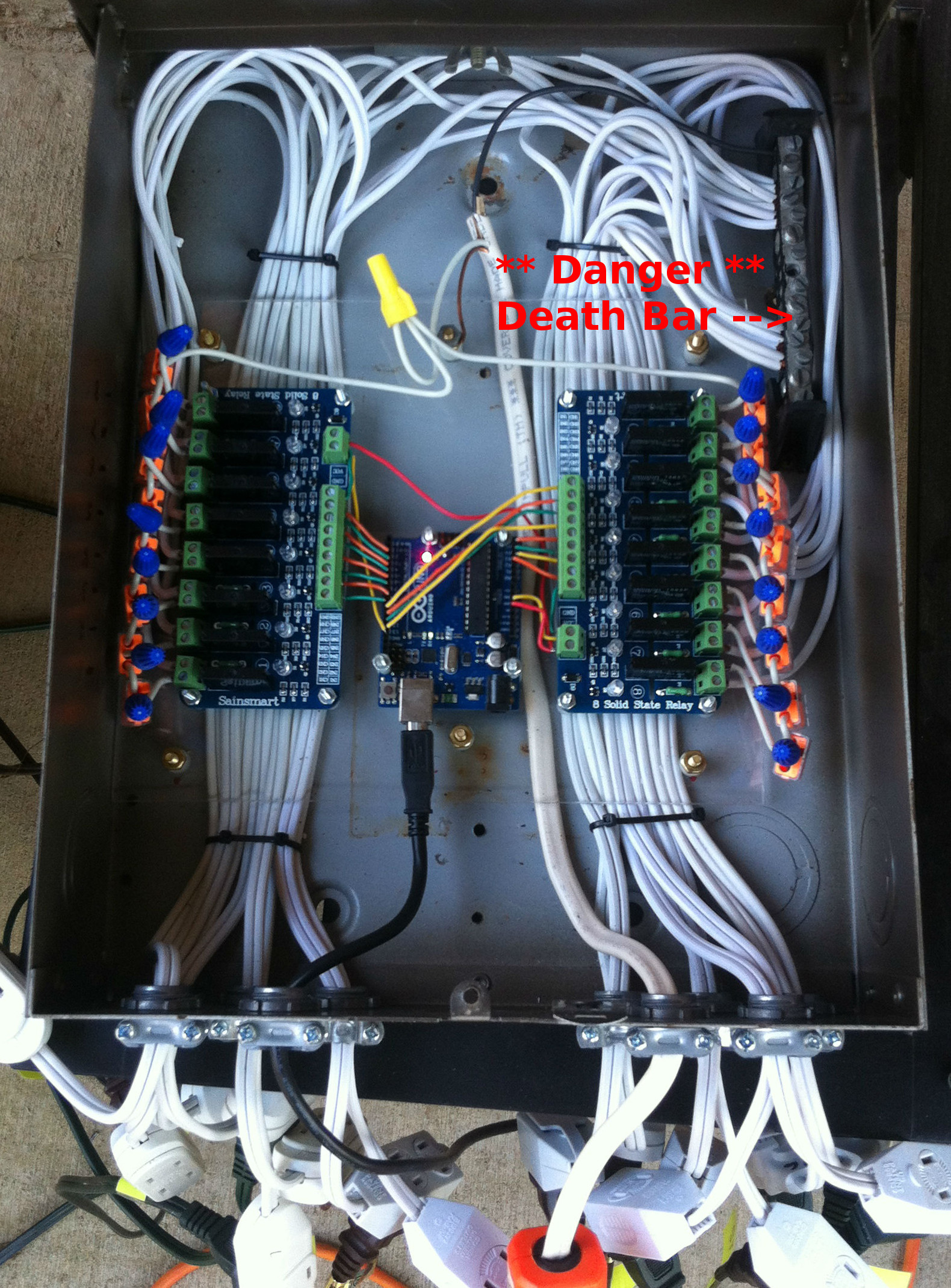
 Figure 4: Wiring
The SSRs
In Figure 3, you’ll notice that the extension cords and 110V supply (orange extension cord) enter the box through the ports on the right. In Figure 4, you can see them running behind the SSRs and that there’s 3 brass screws at the top and bottom of the picture. Those screws (along with nylon risers) support the plexi-glass to which the Arduino and SSRs are mounted (they themselves on risers to allow for cooling), giving the extension cords room to run to the top of the box and tie in to the power-supply-bar (where the incoming 110V supply is distributed amongst all 16 channels that feed the lights). As you can see, there are 8 channels on each board. The sides closest to the Arduino are connected, with 22 gage wire, to the digital I/O pins of the Arduino. The sides closes to the outside edge of the photo are connected to 110V with Romex wire and orange 3-way jumpers.
One thing to keep in mind with these SSRs is that each channel has an max amperage that you can run through it (this model is 2mA I believe). At the most, I’ve been able to chain 6 strands of lights together without blowing one of the relays. I know this because I’ve blown one out by running 7 strands chained together off of one channel. Each strand should have a silver/gold tag near one of the plugs that denotes the total amps for that strand (somewhere in the ballpark of 0.34mA). So, 6 x 0.34mA = 2.04mA, just over the 2mA specs of the relay.
 Figure 5: Overview of Box
The Whole Shebang-a-bang
Ultimately, what’s happening here is as the Arduino receives instructions from Vixen, it turns its 16 digital I/O pins either on or off (as determined by your choreographed light sequence in the Vixen software). If a pin is turned on, 5V flows from the Arduino through those multicolored wires to the SSR board, flipping an internal switch in the relay that’s powerful enough to connect the two sides of the 110V circuit. Then your lights come on outside your house. The Arduino does this 16 times every 50ms. That’s pretty damn impressive for a $15 piece of hardware if you ask me.
Results
 Figure 6: Finished Product
All in all, it took me about 15 hours to stumble my way through the assembly of the box (I spent maybe $60 max), configure the software, write the Arduino sketch and throw together 4 choreographed sequences for a show that lasts around 10 minutes. I also ran two book-shelf speakers to the front porch, went out from the headphones port on my PC to a 100W receiver and cranked up the volume. Another great feature of Vixen is that you can schedule your shows so as long as the PC and stereo are on, you can set it and forget it. I had mine play every night from 5:00 - 9:30, starting every minutes. In between shows, I played a “dummy” sequence that just turned the lights on randomly but no music.
Check out my repositories on Github for further details on the software if you need some guidance (links in the right-hand aside of the page). Happy making!